
 news-CBT Rock PDC Bit Manufacturer
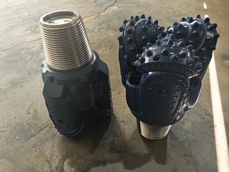
Selecting the right tricone drill bit is essential for maintaining drilling efficiency, controlling bit wear, and achieving consistent penetration rates in different geological formations. However, with numerous bit designs, cutting structures, and bearing configurations available, choosing the right model can be challenging.
The IADC (International Association of Drilling Contractors) roller bit classification system provides a standardized way to identify and compare tricone drill bits. It uses a three-digit code to describe the bit's formation application, cutting structure classification, and bearing or seal configuration. An optional fourth letter can indicate additional design features.
Understanding the IADC classification helps drilling contractors, engineers, and procurement teams identify suitable steel tooth and tungsten carbide insert (TCI) tricone bits for different drilling conditions.
This guide explains the complete IADC coding structure, formation classifications, bearing types, common bit codes, and practical selection considerations.
1. What Is the IADC Tricone Bit Classification System?
IADC stands for the International Association of Drilling Contractors. Its roller cone bit classification system provides a common reference for describing tricone drill bits from different manufacturers.
The system classifies roller cone bits according to three main characteristics:
Formation type and hardness range for which the bit is designed.
Cutting structure classification within that formation range.
Bearing and seal configuration, including gauge protection.
A standard IADC roller bit classification consists of three numerical digits, sometimes followed by an additional letter.
Basic IADC code structure:
| Code Position | Classification | What It Describes |
|---|---|---|
| First digit | Formation series | Cutting structure type and general formation range |
| Second digit | Formation type | Hardness subdivision within the series |
| Third digit | Bearing and bit features | Bearing/seal arrangement and gauge protection |
| Fourth character (optional) | Additional features | Special design characteristics |
For example, IADC 537 can be interpreted as follows:
5: TCI bit designed for soft to medium formations.
3: A more specific formation classification within the fifth series.
7: Sealed friction (journal) bearing with gauge protection.
The three digits should be read together. They provide more information than simply identifying whether a bit is intended for soft or hard rock.
2. First Digit: Formation Series and Cutting Structure
The first digit identifies the general formation series and distinguishes milled tooth bits from tungsten carbide insert bits.
There are eight main series, numbered from 1 to 8.
2.1 Steel Tooth Tricone Bits: Series 1–3
Series 1, 2, and 3 are used for steel tooth, also known as milled tooth, tricone bits.
These bits have steel teeth machined directly into the cone surfaces. The teeth penetrate, scrape, and crush the formation as the three cones rotate.
| IADC Series | Formation Classification | Typical Formation Characteristics |
|---|---|---|
| 1 | Soft formations | Low compressive strength and high drillability |
| 2 | Medium to medium-hard formations | Higher compressive strength than soft formations |
| 3 | Hard formations | Hard, semi-abrasive, and abrasive formations |
Series 1 – Soft Formations
Series 1 steel tooth bits are designed for formations with relatively low compressive strength and high drillability.
Typical formations include:
Soft shale
Claystone
Mudstone
Soft clay-rich formations
Unconsolidated or weakly consolidated sedimentary formations
Their cutting structures generally use longer steel teeth to provide effective penetration and scraping action in softer rock.
Series 2 – Medium Formations
Series 2 steel tooth bits are designed for medium to medium-hard formations with higher compressive strength.
Typical applications may include:
Medium-hard shale
Moderately consolidated sandstone
Medium-hard limestone
Mixed sedimentary formations
Compared with soft-formation steel tooth bits, these designs use cutting structures adapted to greater formation resistance and wear.
Series 3 – Hard Formations
Series 3 steel tooth bits are intended for hard, semi-abrasive, and abrasive formations.
Their cutting structures are designed to withstand greater rock resistance and cutting loads.
Typical formations may include:
Hard sandstone
Hard limestone
Dense sedimentary rock
Hard formations containing abrasive mineral components
2.2 Tungsten Carbide Insert Bits: Series 4–8
Series 4 through 8 are used for tungsten carbide insert (TCI) tricone bits.
Unlike steel tooth bits, TCI bits have separate tungsten carbide inserts pressed into the cone surfaces. These inserts provide high hardness and wear resistance.
Different insert shapes, sizes, and arrangements allow TCI bits to work across a wide range of formation conditions.
| IADC Series | Formation Classification | Typical Formation Characteristics |
|---|---|---|
| 4 | Very soft formations | Low compressive strength and high drillability |
| 5 | Soft to medium formations | Relatively low compressive strength |
| 6 | Medium-hard formations | Higher compressive strength |
| 7 | Hard formations | Hard, semi-abrasive, and abrasive |
| 8 | Extremely hard formations | Very hard and abrasive |
Series 4 – Very Soft Formations
Series 4 TCI bits are designed for very soft formations with low compressive strength.
Typical formations include:
Soft shale
Claystone
Soft mudstone
Weakly consolidated sandstone
Their cutting structures use carbide inserts configured for efficient penetration in formations where steel tooth designs may also be considered.
Series 5 – Soft to Medium Formations
Series 5 TCI bits are designed for soft to medium formations with relatively low compressive strength.
Typical formations include:
Soft to medium shale
Medium-soft sandstone
Soft limestone
Moderately consolidated sedimentary rock
They provide a TCI cutting structure for applications requiring a combination of penetration efficiency and insert wear resistance.
Series 6 – Medium-Hard Formations
Series 6 TCI bits are designed for medium-hard formations with higher compressive strength.
Typical formations include:
Medium-hard limestone
Consolidated sandstone
Dolomite
Medium-hard shale
The carbide inserts are designed to withstand greater formation resistance during drilling.
Series 7 – Hard Formations
Series 7 TCI bits are intended for hard, semi-abrasive, and abrasive formations.
Typical formations include:
Hard limestone
Hard sandstone
Dolomite
Dense and abrasive rock formations
These bits generally use cutting structures designed for higher impact resistance and wear resistance.
Series 8 – Extremely Hard Formations
Series 8 TCI bits are designed for extremely hard and abrasive formations.
Typical applications include drilling through:
Very hard limestone
Hard dolomite
Highly abrasive rock
Dense and competent hard rock formations
The cutting structure and insert configuration are selected to withstand demanding drilling conditions.
Important: Formation series provide general application guidelines. Actual bit performance depends on rock properties, insert geometry, cone design, bearing configuration, drilling parameters, and operating conditions. A higher series number does not automatically mean a bit will perform better in every hard-rock application.
3. Second Digit: Formation Hardness Subclassification
The second digit further divides each formation series into four types, numbered 1 through 4.
Within each series:
Type 1 represents the softest formation subdivision.
Type 2 represents a harder subdivision.
Type 3 represents a still harder subdivision.
Type 4 represents the hardest subdivision within that series.
For example, within the TCI Series 5 classification:
| IADC Second Digit | Formation Subdivision |
|---|---|
| 1 | Softest within Series 5 |
| 2 | Harder than Type 1 |
| 3 | Harder than Type 2 |
| 4 | Hardest within Series 5 |
The same subdivision principle applies to the other formation series.
For example:
IADC 511 belongs to the softest subdivision of the Series 5 TCI formation range.
IADC 513 belongs to a harder subdivision within Series 5.
IADC 517 uses the Type 1 formation subdivision, combined with a different bearing configuration identified by the third digit.
The second digit should always be interpreted within its own first-digit series. Type 2 in Series 5 and Type 2 in Series 7 do not describe the same absolute rock hardness.
This distinction is important when comparing different tricone bit classifications.
4. Third Digit: Bearing, Seal and Gauge Protection
The third digit identifies the bearing and seal configuration, together with the presence or absence of additional gauge protection.
Bearing design is important because it affects the bit's load-carrying capacity, rotation, lubrication, and service life.
The standard IADC roller cone bit classification uses third digits from 1 to 7.
| Third Digit | Bearing Configuration | Gauge Protection |
|---|---|---|
| 1 | Standard open roller bearing | No special gauge protection indicated |
| 2 | Standard open roller bearing for air drilling | No special gauge protection indicated |
| 3 | Standard open roller bearing | With gauge protection |
| 4 | Sealed roller bearing | No special gauge protection indicated |
| 5 | Sealed roller bearing | With gauge protection |
| 6 | Sealed friction (journal) bearing | No special gauge protection indicated |
| 7 | Sealed friction (journal) bearing | With gauge protection |
4.1 Open Roller Bearings
Open bearing tricone bits use an unsealed bearing structure. Drilling fluid or air can circulate around the bearing area depending on the bit design and application.
Common configurations include:
Standard open roller bearings for fluid drilling.
Open roller bearings designed specifically for air drilling.
These bearing arrangements are used in applications where the drilling method and operating conditions are compatible with an open bearing design.
4.2 Sealed Roller Bearings
Sealed roller bearing bits incorporate a sealing system to protect the bearing components from drilling fluid and formation particles.
The bearing system uses rolling elements to support cone rotation and drilling loads.
Sealed roller bearing designs are available with or without additional gauge protection.
4.3 Sealed Friction (Journal) Bearings
Journal bearing bits use a friction-bearing structure instead of the conventional roller-bearing arrangement.
The cone rotates around a journal surface, with a sealing and lubrication system supporting bearing operation.
Journal bearing designs are commonly used in demanding drilling applications where bearing load capacity and durability are important considerations.
4.4 Gauge Protection
Gauge protection helps reduce wear on the outer cutting structure and gauge area of the bit.
In IADC classification, gauge-protected configurations are identified by third digits 3, 5, and 7.
Gauge protection is generally provided through additional tungsten carbide inserts positioned in areas such as the heel of the cone and the shirttail.
This feature helps maintain the bit's gauge diameter during drilling, which is important for borehole size control and bit performance.
5. Optional Fourth Letter: Additional Bit Features
Some IADC roller bit classifications include a fourth character after the three numerical digits.
This character is a letter used to identify additional design features or cutting structure characteristics.
Common letter designations found in IADC reference charts include:
| Letter | Additional Feature |
|---|---|
| A | Air application |
| B | Reinforced welds |
| C | Center jet |
| D | Deviation control |
| E | Extended jet |
| G | Extra gauge protection |
| J | Jet deflection |
| R | Reinforced welds |
| S | Standard steel tooth |
| X | Chisel-shaped insert |
| Y | Conical insert |
| Z | Other insert shape |
The exact letter designations should be checked against the applicable IADC classification reference and manufacturer documentation, as additional designations and conventions may vary.
For example, a bit designation with an additional letter may indicate a particular insert shape, hydraulic arrangement, or other special feature.
The letter suffix supplements the three-digit classification. It does not replace the information provided by the numerical code.
6. Common IADC Tricone Bit Codes Explained
Understanding individual IADC codes makes it easier to compare tricone bits and identify their intended applications.
The following examples illustrate how to read commonly encountered steel tooth and TCI bit classifications.
6.1 Steel Tooth Bit Examples
IADC 114
1: Steel tooth bit for soft formations.
1: Softest formation subdivision within Series 1.
4: Sealed roller bearing without special gauge protection indicated.
This classification represents a soft-formation steel tooth bit with a sealed roller bearing configuration.
IADC 127
1: Steel tooth bit for soft formations.
2: Harder formation subdivision within Series 1.
7: Sealed friction (journal) bearing with gauge protection.
This code identifies a soft-formation steel tooth bit with a sealed journal bearing and gauge protection.
IADC 335
3: Steel tooth bit for hard formations.
3: Harder formation subdivision within Series 3.
5: Sealed roller bearing with gauge protection.
This classification is intended for hard formations where a steel tooth cutting structure is used with a sealed roller bearing and gauge protection.
IADC 337
3: Steel tooth bit for hard formations.
3: Harder formation subdivision within Series 3.
7: Sealed friction (journal) bearing with gauge protection.
6.2 TCI Bit Examples
IADC 517
5: TCI bit for soft to medium formations.
1: Softest formation subdivision within Series 5.
7: Sealed friction (journal) bearing with gauge protection.
IADC 537
5: TCI bit for soft to medium formations.
3: Harder formation subdivision within Series 5.
7: Sealed friction (journal) bearing with gauge protection.
IADC 617
6: TCI bit for medium-hard formations.
1: Softest formation subdivision within Series 6.
7: Sealed friction (journal) bearing with gauge protection.
IADC 837
8: TCI bit for extremely hard and abrasive formations.
3: Harder formation subdivision within Series 8.
7: Sealed friction (journal) bearing with gauge protection.
6.3 Quick Reference Table
| IADC Code | Bit Type | Formation Series | Bearing Configuration |
|---|---|---|---|
| 114 | Steel Tooth | Soft | Sealed roller |
| 127 | Steel Tooth | Soft | Sealed journal |
| 335 | Steel Tooth | Hard | Sealed roller, gauge protected |
| 337 | Steel Tooth | Hard | Sealed journal, gauge protected |
| 517 | TCI | Soft to medium | Sealed journal, gauge protected |
| 537 | TCI | Soft to medium | Sealed journal, gauge protected |
| 617 | TCI | Medium-hard | Sealed journal, gauge protected |
| 837 | TCI | Extremely hard | Sealed journal, gauge protected |
The examples above demonstrate that two bits can share the same formation series while having different second or third digits. Their formation subdivision and bearing configurations therefore need to be considered separately.
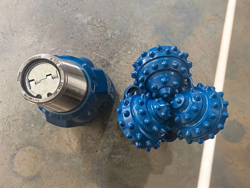
7. Steel Tooth vs. TCI Tricone Bits: How Does IADC Classify Them?
Steel tooth and TCI tricone bits have different cutting structures, and the IADC system identifies this distinction through the first digit.
7.1 Steel Tooth Tricone Bits
Steel tooth tricone bits, also known as milled tooth tricone bits, have teeth machined directly into the cone surfaces.
The steel teeth are hardened to improve wear resistance and provide effective cutting action in softer formations.
Their main IADC formation series are:
Series 1: Soft formations.
Series 2: Medium to medium-hard formations.
Series 3: Hard formations.
Steel tooth bits are commonly selected for drilling applications involving claystone, shale, mudstone, and other suitable sedimentary formations.
7.2 TCI Tricone Bits
TCI tricone bits use tungsten carbide inserts pressed into the cone surfaces.
The inserts are available in different shapes and sizes, including conical and chisel-shaped designs.
Their main IADC formation series are:
Series 4: Very soft formations.
Series 5: Soft to medium formations.
Series 6: Medium-hard formations.
Series 7: Hard formations.
Series 8: Extremely hard formations.
TCI bits are widely used in drilling applications requiring greater insert wear resistance, particularly in medium-hard, hard, and abrasive formations.
7.3 Comparison Table
| Feature | Steel Tooth Tricone Bit | TCI Tricone Bit |
|---|---|---|
| Common name | Milled tooth bit | Tungsten carbide insert bit |
| Cutting structure | Machined steel teeth | Tungsten carbide inserts |
| IADC series | 1–3 | 4–8 |
| Typical application | Soft to hard formations, depending on design | Very soft to extremely hard formations, depending on design |
| Main cutting action | Scraping and crushing | Crushing and indentation |
| Key consideration | Tooth wear and formation compatibility | Insert geometry, impact resistance, and wear resistance |
The choice between steel tooth and TCI bits depends on formation properties, cutting structure design, drilling parameters, and the required service life.
A TCI bit is not automatically the best choice simply because it uses tungsten carbide inserts. In some soft formations, a properly designed steel tooth bit can provide higher penetration efficiency.
8. How to Select the Right IADC Tricone Bit
IADC classification provides a useful starting point, but choosing the right bit requires more than matching a code to a formation name.
Several drilling factors should be evaluated together.
8.1 Identify Formation Hardness
Formation hardness is one of the main factors influencing bit selection.
Soft formations generally require cutting structures that provide efficient penetration and adequate chip removal.
Hard formations require cutting structures capable of withstanding higher compressive loads and impact forces.
Typical selection considerations include:
Soft clay and shale: Consider suitable soft-formation steel tooth or TCI bits.
Medium-hard sandstone and limestone: Consider medium-formation TCI or suitable steel tooth designs.
Hard limestone and dolomite: Consider hard-formation TCI bits.
Extremely hard and abrasive rock: Evaluate Series 8 TCI designs and their specific insert configurations.
8.2 Evaluate Rock Abrasiveness
Two formations with similar hardness can produce different bit wear rates because of differences in mineral composition and abrasiveness.
Highly abrasive formations can accelerate insert wear, tooth wear, and gauge reduction.
When drilling abrasive rock, consider:
Carbide insert grade and geometry.
Gauge protection.
Bearing and seal design.
Expected drilling duration.
Historical bit performance in similar formations.
8.3 Choose the Appropriate Bearing Structure
Bearing configuration should match the drilling method, operating load, and expected drilling conditions.
Open bearing bits may be appropriate for certain applications, including air drilling designs.
Sealed roller and journal bearing bits are commonly considered for applications requiring protected bearing systems and longer operating life.
The selection should also account for rotary speed, weight on bit, drilling fluid, and operating temperature.
8.4 Consider Drilling Parameters
The performance of a tricone bit is strongly affected by operating parameters.
Important factors include:
Weight on Bit (WOB): The axial load applied to the bit. Appropriate WOB depends on bit diameter, cutting structure, formation strength, and drilling equipment.
Rotary Speed (RPM): The rotational speed influences cutting frequency, penetration rate, and wear. The suitable RPM range depends on the bit design and formation conditions.
Drilling Fluid and Circulation: Drilling fluid or air circulation removes cuttings, cools the cutting structure, and helps maintain effective drilling conditions.
Hydraulic Performance: Nozzle configuration and available flow rate affect bottom-hole cleaning and cuttings removal.
These operating factors should be considered together with the IADC classification when selecting a bit.
9. IADC Bit Classification vs. IADC Dull Grading: What Is the Difference?
The IADC bit classification system and the IADC dull grading system are two separate tools used in drilling operations.
They serve different purposes.
IADC Bit Classification
The three-digit IADC classification identifies the bit's design characteristics.
It describes:
Formation series.
Formation hardness subdivision.
Bearing and seal configuration.
Additional features when a fourth letter is used.
For example, IADC 537 identifies a TCI bit designed for the Series 5 formation range, with a Type 3 formation subdivision and a sealed journal bearing with gauge protection.
IADC Dull Grading
IADC dull grading is used to evaluate a drill bit after it has been removed from the borehole.
It records the condition of the cutting structure, bearings, gauge, and other components, together with the reason the bit was pulled.
The commonly used IADC dull grading system contains eight reporting positions:
| Position | Description |
|---|---|
| 1 | Inner cutting structure condition |
| 2 | Outer cutting structure condition |
| 3 | Dull characteristics |
| 4 | Location of the damage or wear |
| 5 | Bearings and seals |
| 6 | Gauge condition |
| 7 | Other dull characteristics |
| 8 | Reason for pulling the bit |
For the first two positions, a numerical scale from 0 to 8 describes cutting structure wear.
For example:
0 indicates no cutting structure loss.
8 indicates complete cutting structure loss or severe wear.
The bearing and seal condition, gauge reduction, and other damage are recorded separately using their designated codes.
Dull grading helps drilling teams evaluate bit performance, identify failure mechanisms, and improve future bit selection.
In short: IADC bit classification describes what a bit is designed to do, while IADC dull grading describes what happened to the bit after drilling.
10. Frequently Asked Questions About IADC Tricone Bit Classification
Q1: What does IADC stand for in tricone drill bits?
IADC stands for the International Association of Drilling Contractors. Its roller cone bit classification system provides a standardized method for identifying tricone drill bit designs according to formation application, cutting structure classification, and bearing configuration.
Q2: What is the difference between IADC 1–3 and IADC 4–8?
IADC Series 1–3 are used for steel tooth or milled tooth tricone bits. Series 4–8 are used for tungsten carbide insert (TCI) tricone bits.
The series also indicate different formation application ranges, from soft formations to extremely hard and abrasive formations.
Q3: What does the second digit in an IADC code mean?
The second digit classifies the formation hardness within the selected series. It ranges from 1 to 4, with 1 representing the softest subdivision and 4 the hardest subdivision within that series.
Q4: What does the third digit in an IADC code represent?
The third digit identifies the bearing and seal configuration, as well as whether gauge protection is included. The standard classifications range from 1 to 7.
Q5: What is the difference between IADC 517 and IADC 537?
Both are TCI tricone bits in the Series 5 formation range and use sealed journal bearings with gauge protection.
The difference is the second digit. IADC 517 belongs to the softest formation subdivision within Series 5, while IADC 537 belongs to a harder subdivision.
Q6: Which IADC classification is suitable for hard rock drilling?
Series 7 and 8 TCI bits are commonly associated with hard and extremely hard abrasive formations. However, the appropriate code depends on the actual rock properties, insert configuration, drilling parameters, and bearing design.
Q7: Can a TCI tricone bit be used in soft formations?
Yes. Series 4 and 5 TCI bits are designed for very soft and soft-to-medium formations. TCI bits are not exclusively used for hard rock drilling.
Q8: Does a higher IADC number always mean better drilling performance?
No. A higher series number indicates a different formation application range, not a universal improvement in bit quality or drilling performance. The right bit must match the formation and operating conditions.
Q9: What is the difference between IADC classification and dull grading?
IADC classification identifies the original bit design, while dull grading records the bit's condition after use, including cutting structure wear, bearing condition, gauge reduction, and the reason for pulling the bit.
Conclusion
The IADC tricone bit classification system provides a practical framework for understanding roller cone drill bit designs and matching them to drilling conditions.
The first digit identifies the formation series and cutting structure type, the second digit further classifies formation hardness, and the third digit describes the bearing and gauge protection configuration. An optional fourth letter provides additional design information.
For drilling contractors and procurement teams, understanding these codes makes it easier to compare steel tooth and TCI tricone bits, evaluate bearing configurations, and select suitable products for different geological formations.
However, the IADC code should always be considered together with the actual cutting structure, formation characteristics, drilling parameters, and operating requirements.
When selecting a tricone drill bit, providing the required diameter, IADC classification, API thread connection, and formation information helps suppliers identify a suitable configuration for the drilling project.